Producing the volumetric lighting effect is a multi-step process that can be simplified as:
Detect edges in the shadow map
Tesselate a light-space plane along detected edges
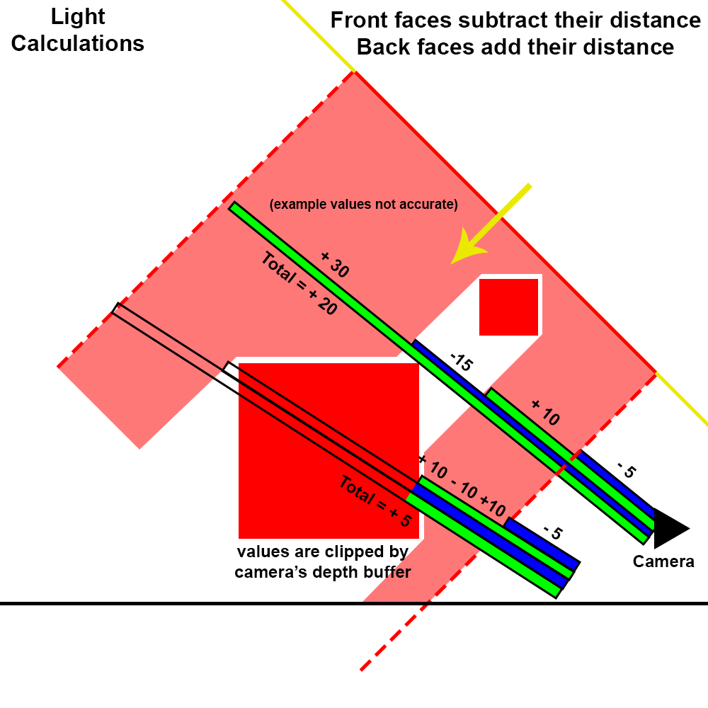
Project the plane into the scene and use it to gather depth data
Use the depth data to calculate atmospheric conditions for each texel
Overlay the atmosphere onto the camera’s output
These steps are covered in-depth below, however, I hope to make more detailed explanations of many of these steps in the future.
First, for clarity we can define each coordinate space we’ll be using:
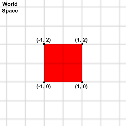
World Space
The global coordinate system used by Unity.
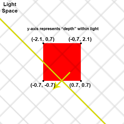
Light Space
Light-space is essentially world-space that is aligned to the direction of the main light. We can use this to get a corrected light-depth from each cascade.
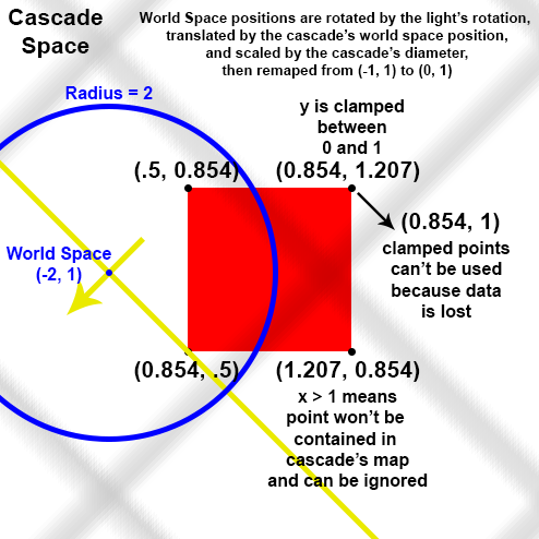
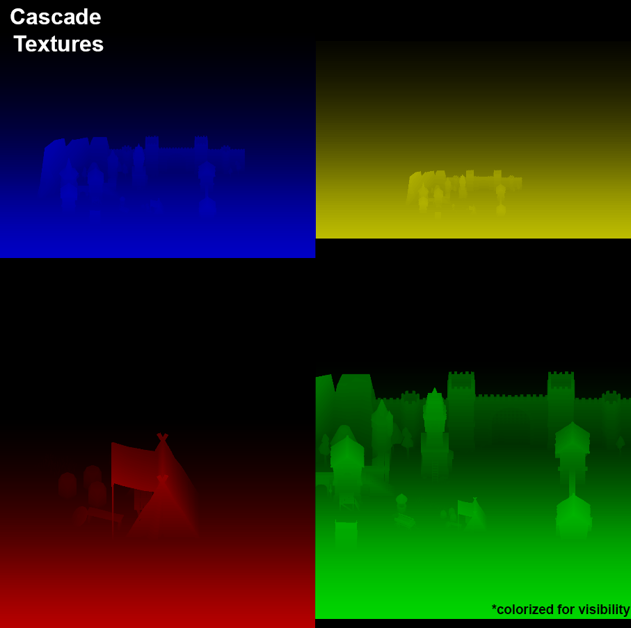
Cascade Space
The coordinate system defined by each cascade in the shadow map. Shadows are orthographically projected along the direction of their light source, so each cascade will have the same rotation. However, cascades vary in their scale and translation depending on the area they are trying to cover.
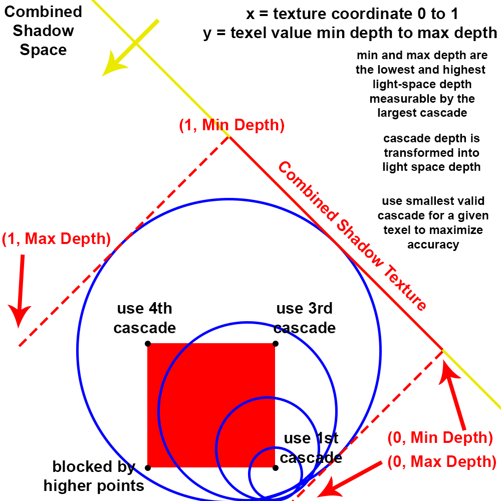
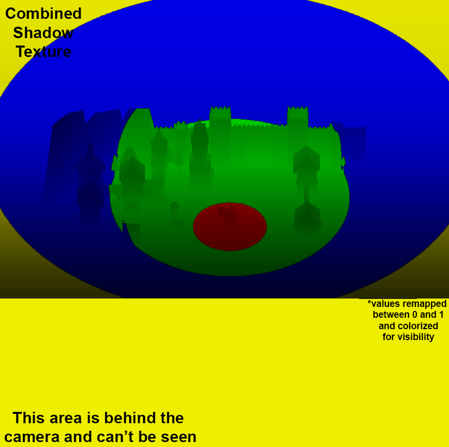
Sampling the Cascades
In order to perform edge detection on the shadow map, we must find a way to seamlessly combine all cascades into a new texture. Our new texture will cover the desired area of our volumetric system in light space. Each cascade exists in its own coordinate space, so we need to be able to transform from cascade-space to light-space for each texel in our new texture. Because cascades can overlap in their coverage, we also need to select the correct cascade for our sampled point. The current implementation of this is rather involved and likely could be made more efficient, so I’ll avoid covering it for now. After we have selected the correct light-space position for each texel, we should have our combined shadow texture.
Laplacian Edge Detection
A new texture is generated by performing Laplacian edge detection on the combined shadow texture. The kernel size and standard deviation is user defined to make edge detection more or less sensitive as desired. mip-maps of the Laplacian are then created down to the width of the base mesh (described later). The laplacian texture and all of its mip-maps are actually stored in a buffer to increase performance by reducing uploads to the GPU.
Generate Base Mesh
Mesh data is stored in packed integers. The size of the base plane to be tesselated is determined by the user. Each integer represents a quadtree section used for parallelized generation of the mesh in the next step.
Generate and Render the Mesh
The mesh is generated in a ping-ponged operation until the desired level of detail is reached. While generating the mesh, if it is determined that a quad won’t be further subdivided, it is ready to be rendered and added to a rendering buffer. The buffer then renders any new quads for that ping-pong level. All rendered quads are accumulated in a depth buffer. The rendering is done through an indirect call, all to reduce uploads to the GPU. The walls must also be rendered at the same time if necessary. The ceiling is rendered before anything else.
Cleanup
The rendered mesh texture occasionally has pixel-sized holes likely due to floating-point precision. To remedy this, the texture is fed through a patching algorithm that analyses all neighboring pixels and fills with the nearest value if beyond a given threshold of difference.
Depth Blur
Texture is blurred based on camera’s depth buffer.
Upsample
Texture is upsampled to screen resolution, but uses the depth buffer to intelligently select the best pixel to sample.
Composite
Volume is calculated using the accumulated depth of the upsampled texture, then composited onto the main camera’s texture.